Organization & Contact
Benjamin Böhm – Reaktive Strömungen und Messtechnik, Technische Universität Darmstadt, Otto-Berndt-Str. 3, 64287 Darmstadt Germany; boehm@rsm.tu-…; +49 6151 16 28913
Brian Peterson – Mechanical Engineering, School of Engineering, University of Edinburgh, The King’s Buildings, Mayfield Road, Edinburgh, EH9 3JL, Scotland, UK brian.peterson@ed.ac.uk
Sponsors
The organizers of the workshop like to express their thanks to the sponsors of the workshop, the Technische Universität Darmstadt and the Deutsche Forschungsgemeinschaft (DFG) through the Collaborative Research Centre/Transregio 150: Turbulent, chemically reacting multiphase flow near walls for their support.
Preface
The Darmstadt Engine Workshop is an academic approach to improve the methods used to predict and investigate turbulent flows within the engine research and design process. The aim of this collaborative effort is to learn more about the detailed physics of reacting and non-reacting flows in internal combustion (IC) engines. This effort does not focus on the design of new engines or engine technology. The workshop is therefore open to everyone from academia only. This workshop encompasses both experimental and theoretical development, which includes logical collaborations (worldwide) to form strong teams that jointly address the challenges of combustion science within IC engines.
Aim of the Darmstadt Engine Workshop (DEW)
The aim of the Darmstadt Engine Workshop (DEW) is to facilitate a close collaboration and information exchange between the experimental and modeling efforts for IC engine flows and combustion. Simulations and experiments are acknowledged to be complimentary powerful tools providing new insights into engine combustion processes. The global aim of this workshop is to take advantage of both tools for a more detailed understanding of IC engine sub-processes.
Up to date, engine simulations are not fully predictive and require validation first. To our understanding a validated simulation should ideally capture the entire volume domain over the entire cycle correctly. Additionally sensitivities regarding model parameters and boundary conditions should be characterized. The strategy of this workshop is to provide comprehensive validation sequences with increasing complexity, starting from the motored engine flow (i.e. non-reacting) and progressing towards engine combustion with direct injection. Each validation sequence comprises an iterative process of validation, identifying open issues, improving modeling and providing additional experimental data if required. Once validated, the simulation data can provide new insights into the three-dimensional in-cylinder processes giving access to regions and quantities which are not accessible with experimental methods. Thus the simulation data will provide detailed information for an improved understanding of in-cylinder processes and for the design of experiments.
To achieve this goal we are focusing on an optically accessible single-cylinder spark ignition engine with well-defined boundary conditions and reproducible engine operation. The already existing comprehensive dataset is continuously expanded addressing as many quantities and details as possible and adding step by step relevant engine processes.
The Experimental setup
The engine test bench
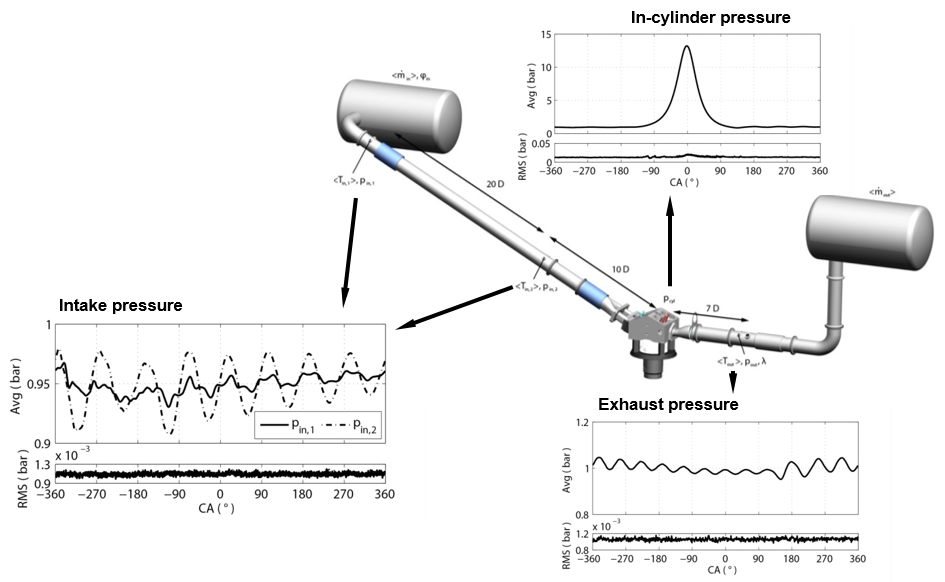
The motivation of this test bench is to enable reproducible engine operation for a large variation of measured quantities, while resolving a plurality of parameters and characterizing engine operation. It allows conditioning the intake air in terms of pressure, temperature and gas composition, port fuel injection of liquid and gaseous fuels, direct-injection, as well as reliable boundary condition control and measurement. Further details of the intake and exhaust systems were designed to provide reproducible thermodynamic and flow boundary conditions and simplified meshing for three-dimensional engine flow simulations. Figure 1 shows a schematic of the engine test bench from the intake to the exhaust plenum. It shows the locations for which fluid dynamic and thermodynamic conditions were measured during engine operation together with examples of pressure traces.
The optical engine
The engine is an optically accessible single-cylinder direct injection spark ignition engine. The engine features a twin-cam, overhead-valve pent-roof cylinder head, a 55 mm height quartz-glass cylinder liner with 8 mm window extension into the pent-roof, and a Bowditch piston arrangement with flat quartz-glass piston-crown window (75 mm diameter). The engine's bore and stroke are 86 mm with a displacement volume of 499.6 cm³. More details on the engine test bench are presented in Baum et al. [1].
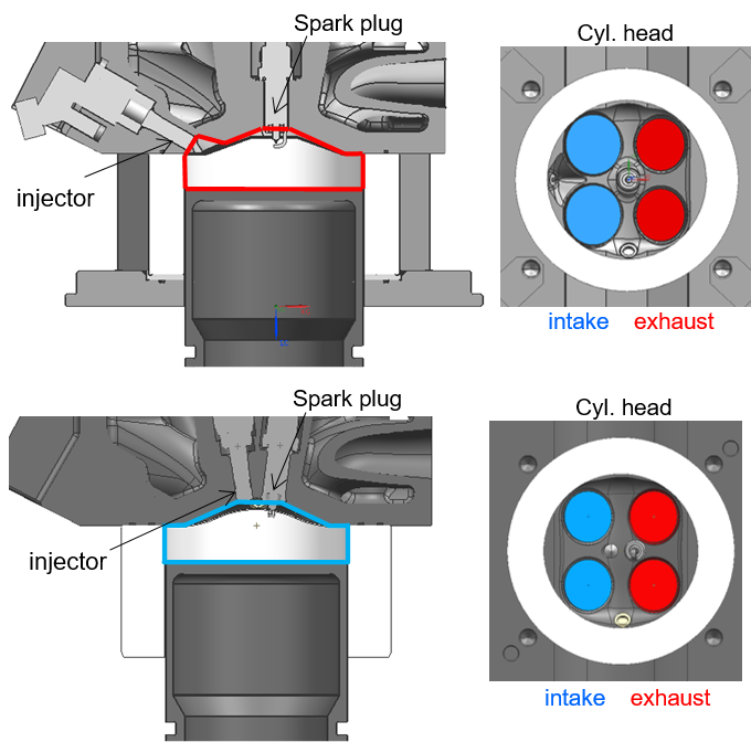
Two cylinder-head geometries are available: The first is a wall-guided cylinder-head equipped with a side-mounted fuel injector, a centrally located spark plug, and dual intake valves (33 mm diameter) and exhaust valves (29 mm diameter) located on opposite sides of the spark plug. The second is a spray-guided cylinder head equipped with a centrally mounted fuel injector, centrally located spark plug, and dual intake valves (29 mm diameter) and exhaust valves (29 mm) in the same arrangement as the wall guided configuration. More details on the cylinder-heads together with a flow field comparison can be found in Freudenhammer et al. [2].
The standard operational conditions for motored engine operation:
| RPM | 800 +/- 7 min-1 |
| Cyl. Head, coolant temp. ( <Teng> ) | 60 +/- 1 °C |
| Avg. Press. Intake 1 ( pin,1 ) | 0.95 +/- 0.002 bar |
| Avg. Press. Intake 2 ( pin,2 ) | 0.95 +/- 0.002 bar |
| Avg. Press. Exhaust ( pout ) | 1.00 +/- 0.016 bar |
| Intake temp. 1 ( <Tin,1> ) | 22.9 +/- 0.1 °C |
| Intake temp. 2 ( <Tin,2> ) | 23.2 +/- 0.1 °C |
| Exhaust temp. ( <Tout> ) | 43.7 +/- 0.5 °C |
| Mass air in ( <min> ) | 11.5 kg/h +/- 2% |
| Mass air out ( <mout> ) | 11.5 kg/h +/- 2% |
| Humidity (PHi) | 1.8 %-RH |
| Intake valve open (IVO) | 325 °aTDC |
| Intake valve close (IVC) | 125 °bTDC |
| Exhaust valve open (EVO) | 105 °aTDC |
| Exhaust valve close (EVC) | 345 °bTDC |
Publications
[1] Baum E, Peterson B, Böhm B, Dreizler A. On The Validation of LES Applied to Internal Combustion Engine Flows: Part 1: Comprehensive Experimental Database. Flow Turbulence Combust 2014;92:269–97.
[2] Freudenhammer D, Peterson B, Ding C, Boehm B, Grundmann S. The Influence of Cylinder Head Geometry Variations on the Volumetric Intake Flow Captured by Magnetic Resonance Velocimetry. SAE Int. J. Engines 2015;8.
[3] Zentgraf F, Baum E, Böhm B, Dreizler A, Peterson B. Analysis of the turbulent in-cylinder flow in an IC engine using tomographic and planar PIV measurements. 17th Int Symp on Applications of Laser Techniques to Fluid Mechanics Lisbon, Portugal, 07-10 July, 2014.
[4] Peterson B, Baum E, Böhm B, Dreizler A. Early flame propagation in a spark-ignition engine measured with quasi 4D-diagnostics. Proceedings of the Combustion Institute 2015;35:3829–37.
[5] Baum E, Peterson B, Surmann C, Michaelis D, Böhm B, Dreizler A. Tomographic PIV measurements in an IC engine. 16th Int Symp on Applications of Laser Techniques to Fluid Mechanics Lisbon, Portugal, 09-12 July, 2012.
[6] Baum E, Peterson B, Surmann C, Michaelis D, Böhm B, Dreizler A. Investigation of the 3D flow field in an IC engine using tomographic PIV. Proceedings of the Combustion Institute 2013;34:2903–10.
[7] Peterson B, Baum E, Böhm B, Sick V, Dreizler A. High-speed flow and temperature imaging of fuel injection in a direct-injection spark-ignition engine. 11th Int. Congress Engine Combust. Processes, Ludwigsburg 2013.
[8] Peterson B, Ding C. Influence of direct-injection on the volumetric flow field in a gasoline engine captured by tomographic PIV. 12th Int. Congress Engine Combust. Processes, Ludwigsburg 2015.
[9] CSO. Piston Surface Temperatures during Flame Impingement captured by High-Speed Phosphor Thermometry.
[10] Freudenhammer D, Baum E, Peterson B, Böhm B, Grundmann S. Towards time-resolved magnetic resonance velocimetry for IC engine intake flows. 10th International ERCOFTAC Symposium on Engineering Turbulence Modelling and Measurements, Marbella, Spain, 17 – 19 Sept 2014.
[11] Freudenhammer D, Baum E, Peterson B, Böhm B, Jung B, Grundmann S. Volumetric intake flow measurements of an IC engine using magnetic resonance velocimetry. Exp Fluids 2014;55.
[12] Peterson B, Baum E, Böhm B, Dreizler A. Simultaneous dual plane OH-LIF and stereoscopic PIV measurements of flame propagation in a spark-ignition engine. European Combustion Meeting, Lund, Sweden, 25.-28. June 2013.
[13] Peterson B, Baum E, Böhm B, Sick V, Dreizler A. High-speed PIV and LIF imaging of temperature stratification in an internal combustion engine. Proceedings of the Combustion Institute 2013;34:3653–60.
[14] Peterson B, Baum E, Böhm B, Sick V, Dreizler A. Evaluation of toluene LIF thermometry detection strategies applied in an internal combustion engine. Appl. Phys. B 2014;117:151–75.